How does IFC work?
Nowadays the BIM method (Building Information Modelling) is inevitable in the construction industry. In many countries, the use of BIM models is planned to be introduced and required soon as the official documentation of the construction project. That’s where IFC plays a vital role.
The role of IFC in BIM
Anyone who works with AEC software (architects, structural engineers, mechanical engineers, project managers, etc.) definitely comes across the concept of BIM and uses it in their daily work routines. The direct way of data exchange between BIM models used by different stakeholders is rather difficult, almost impossible.
There are many types of software and as a consequence, there are many different ways of describing a project structure or even a model element. Furthermore, sharing models and data directly between applications is a time-consuming process and requires unique solutions from all software producers
We can easily realise that a common language is needed that every participant can understand and speak. In the field of BIM, this is the IFC (Industry Foundation Class) standard, which is an open standard and would be the base of the BIM data exchange methods, and the communication among different stakeholders.

Communication within a project
Within a project, there are two ways of communications: Global Communication when all the stakeholders are involved, and Direct Data Exchange when a group of participants share data among themselves.
A common workflow could be when an architect prepares a BIM model, then exports it to an IFC file and shares it with other designers. The IFC is used as a reference for participants to build up their own model.
An example of direct communication is the data exchange between structural designer and producer. Formally the designer generates 2D plans from the BIM model, which is adjusted to industrial requirements. However, a properly exported BIM model contains all the important information for production, and a bunch of information content of the model is no longer utilised.

Besides, generating 2D plans is a significant extra effort for designers too. Practically modelling in three dimensions could reduce the geometry failures with clash detection, for instance, handle the emerging modifications in an easier way, and give a better understanding of the model element for producers and constructors as well. Overall, these are optional data supplies and not part of the official concept.
Another important approach is the possibilities of data exchange between analytical and detailer models. Finite Element Model (FEM) objects are defined with axes and are extremely sensitive for eccentricities. Regardless of the way of the data exchange it is rather difficult to import and export the models without geometry inaccuracies.
In this field, the i/o processes are not developed except for a few examples, where the model transitions are solved with direct data exchange.
Developing IFC File standards
The IFC file and its standard has been developed by BuildingSmart (previously International Alliance for Interoperability was a consortium founded by Autodesk) since 1994 to make a global standardised tool that could support and monitor construction progress and life cycle of buildings (even bridges and infrastructural objects) from the concept and design through the construction to the operation and even demolition.
IFC files could be saved as various formats depending on the size of the model, or what formats are supported by different software. Beyond the official formats (.ifc, .ifcxml, .ifczip) there are temporary and experimental formats too (.json, .hdf, .sqlite), which are currently candidates or unsupported.
The official formats are the following:
- STEP file (.ifc) – the most widely used in practice, based on the ISO standard for clear text representation of EXPRESS data model
- XML (ifc.XML) – gives better readability, but in general, it has 13% larger size than ifc file, based on ISO standard for representation of STEP in XML format
- ZIP (.ifcZIP) – ifc data compressed in ZIP format, the size is comparable
The main versions of IFC files are: IFC 1.5.1 (1988), IFC 2.0 (1999), IFC2x (extension), IFC2x2, IFC2x3 (2006), IFC2x3 TC1 (corrigendum of IFC2x3), IFC4 (formerly IFC2x4, 2013). The IFC2x3 version was submitted to ISO first time which was a big step forward to standardisation. The IFC4 version was approved as a full international standard (ISO 16739:2013). IFC5 is in the planning phase, which will integrate bridges and infrastructure domains.
The IFC structure hierarchy
The IFC file is based on the EXPRESS schema, and it is a rather complicated hierarchy of objects, which describes entities and attributes and their relationships within the model. The EXPRESS is an ISO standardised data modelling language, which defines the connections among the object data.
The main type of entities is the IfcRoot, which is the basic and abstract root class of all entities. They are defined with a globally unique id, name and description. Rooted entities derived from IfcRoot could be created independently, while non-rooted entities only exist if referred from a rooted instance directly or indirectly.
Three abstract subcategories of IfcRoot are defined, IfcObjectDefinition, which describes object occurrences and types, IfcRelationship, that captures the relationships between them and IfcPropertyDefinition, which represents the properties and attributes of objects.
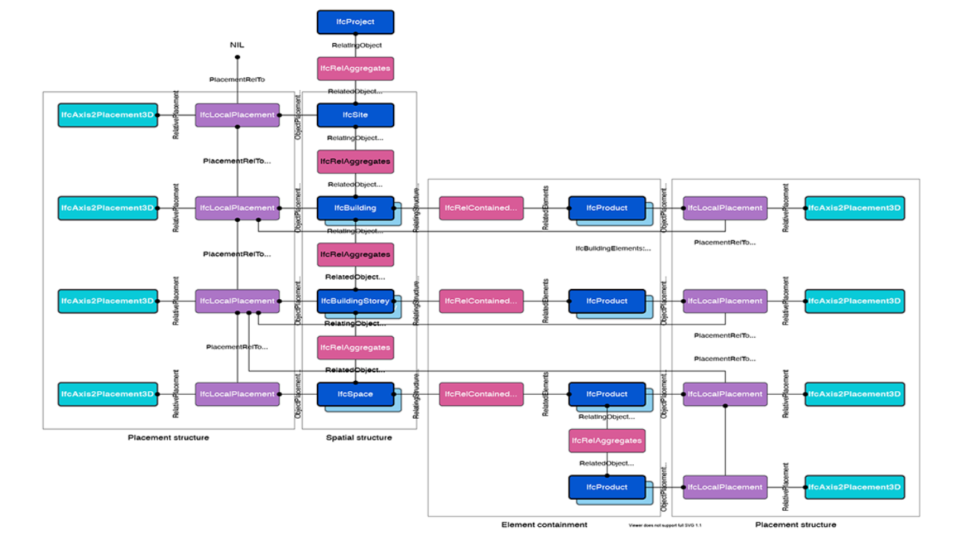
Each isolated element in the model is included in IfcObject entity which is an independent piece of information that might contain or refer to other pieces of information. Exactly one instance of IfcProject, a subtype of IfcObject is mandatory in every IFC model.
It is used as a reference to the root of the spatial structure of a building and defines default units with IfcUnitAssignment objects. Another subclass of IfcRoot – among many of them – is the IfcProduct entity, which is the base class of physical objects. It has material, geometric representation and position in the model space.
It is subdivided into spatial structure elements, physical building elements, distribution elements and other concepts. Spatial structure elements (site, building, building storey, space) that are related to one another and their relationships are defined with IfcRelAggregates.
A building object may contain more than one storey or other buildings, stories may contain spaces and even other stories as well. Physical building elements could be IfcWall, IfcSlab, IfcBeam, IfcColumn, IfcWindow, or IfcFurnishingElement objects which are the generalisation of all furniture-related objects, or even IfcDistributionElement that involves all the electrical, plumbing and HVAC objects.
The geometric shape of an object is defined with representation and described with an IfcShapeRepresentation instance. These are specified in a local coordinate system of the object, which is relative to the related spatial element or container instance. For example, if we want to get the absolute location of an element, we need to roll back the relative local placements to the base object, which could be a site or a building.
Building composition
Bigger and more difficult structures are being built, which makes the BIM method a default and primary concept in the construction industry.
Furthermore, it might be an essential procedure for bridges and infrastructure buildings too. It is rather important to coordinate the large number of participants and to manage documents and plans easily. The further development of the IFC will be the key to achieve the maximum efficiency.
For more articles from the same category
visit BIM Basics and its implementation
You might also be interested in…